FLOW CONDITIONER
In any industry the pipe line contains so many fittings, valves & so many obstructions. The fluid fluid passing through the pipeline gets disturbed after passing through them. For measurement, such disturbed flow is not at all usable. The turbulence/swirl in the flow shall be reduced to acceptable limits before it passes through the instrument. The possible way to achieve this is to provide sufficient straight length or to install flow conditioner before the measuring instrument.
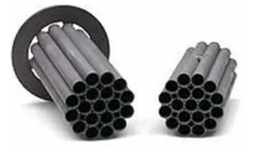
Flow straighterner is a device which removes or significantly reduces swirl in the flow section, caused by various obstructions, fittings, valves etc.
Flow conditioner is a device which, in addition to meeting the requirement of removing or reducing the swirl, is designed to redistribute the velocity profile.
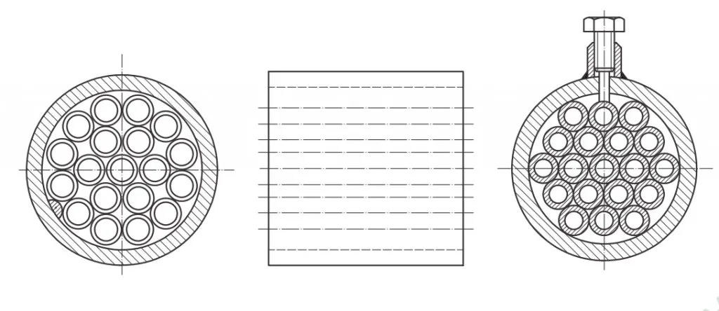
TUBE BUNDLE FLOW STRAIGHTENER
Tube bundled flow straightener consists of bundle of parallel & tangential tubes fixed together & held rigidly in the pipe.
There should be atleast 19 tubes in a bundle.
The length of tubes shall be 2D-3D, where D = pipe ID.
These tubes shall be joined together to make it an assembly & then inserted in the line
Depending upon the fitment in the line the bundle can be either suitable for mounting between flanges or welded in the pipe or fitted & held rigidly inside the pipe. While manufacturing the care shall be taken so that all the tubes are parallel & tangential, otherwise the tube bundle straightener itself will create swirl instead of reducing it.
The pressure loss coefficient (K) for the straightener depends upon the number of tubes selected. Typically for 19 tube bundle straightener, K = 0.75.
FLOW CONDITIONER PLATE
The flow conditioner plate is made up by making number of certain sized holes at PCD defined in ISO 5167.
The plate thickness of the plate shall be maintained between 0.12D & 0.15D. Preferably the thickness is maintained as D/8.
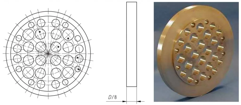
ZANKAR flow conditioner plate consists of 32 number of holes arranged in a symmetrical circular pattern. The diameter & the PCD are a function of pipe ID ‘D’.
The pressure loss coefficient of ZANKAR flow conditioner plate is approximately = 3
The installation of flow straightner or flow conditioner shall be done on upstream of the flow measuring instrument. The distance to be maintained between the fitting & the flow instrument shall be as guided in ISO 5167
CONDENSATE POT
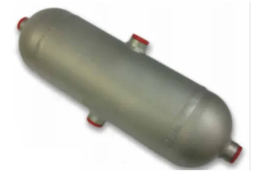
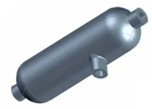
Condensate pot & seal pot are the same based on the shape & construction. Based on the application, they are classified as mentioned under.
Condensate Pots are used to collect and accumulate condensate and extrinsic par ticles. Condensate chambers aid in protecting delicate instruments with smaller orifices from becoming damaged or clogged by foreign debris. The bottom connection is used as a drain port to remove condensate. Condensate chambers can also be used to cool very high temperature liquids.
Seal pots are used to provide a liquid seal between the process instrument and gases such as steam. Its function is to keep the liquid level constant in the impulse tubes (sensing lines), while preventing stem or corrosive liquids from reaching the instrument.
Condensate Chambers & Seal Pots are fabricated from seamless pipe. A variety of materials and wall thicknesses are available to meet a customer’s design pressure and temperature.
SPECIFICATIONS
- Size: 3: & 4”
- Pipe schedule : As per pressure & temperature of flowing fluid.
- Length: 300mm (as a standard practice)
- Pressure tapping: ½” NPT (F), 04 nos
- Material: Pipe: SA106Gr.B, SA335P11, SA335P22.
- Dish end: SA234 Gr. WPB, SA234 Gr. WP11, SA234 Gr. WP22.
(*** For any other specifications mentioned above, please consult factory.)
The material of the condensate pot is selected as per the process temperature and the service compatibility.
TESTING & CERTIFICATIONS APPLICABLE
- Hydro pressure test
- Radiography for butt weld joints.
- Dye-Penetrant test.
- IBR certification

